Installing An Internal USB 2.0 Hub
Caution - not for those of a nervous disposition!
When I installed my internal USB sockets I discovered one of the ones on the main board was faulty, so I had to come up with another plan to get both of my new internal ones working. Answer: an internal USB hub!
So the plan: fit a hub; Connect the "up-stream" port to the working USB port on the main board; connect 2 of the "down-stream" ports to my USB sockets. Easy.
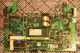
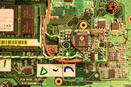
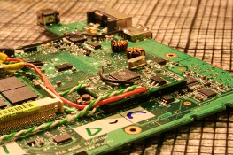
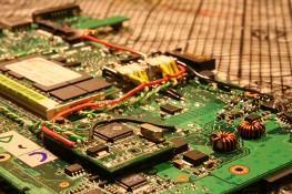
I didn't document this procedure as well as the fitting of the sockets, so all I can provide is 4 photos taken from different angles showing the final assembly.
There are many places inside the Eee that you can fit a hub - you don't necessarily have to put one in the same place as me. However, using double sided sticky tape is a good way to mount it!
So here's how I did it - see how to dismantle the Eee first and then read on ...
Tools required
- No.1 Philips screwdriver (not pozidrive)
- Anti-static wrist band
- Small flat screwdriver
- Fine tipped soldering iron (0.5mm)
- 30awg solder
- Liquid flux
- 30awg wire (green and white) for USB signals
- 24awg / 26awg wire (red and black) for USB power
- Wire strippers
- Tweezers
- Hot glue gun (with glue)
- Magnifying glass
- digital multi-meter
- double sided sticky tape
Preparation
As before, twist some lengths of green and white wire together, then strip and tin the ends of them.
Choosing a USB hub
There are many USB 2.0 hubs out there, but the primary consideration here is the size of the PCB inside it - the smaller, the better. I chose one of the small black cubes with 4 swiveling ports. I bought it from Maplin for £9.99. The sockets are connected to the PCB with wires, which means that the PCB will be smaller than most with the sockets directly attached.
A word of caution though - get a digital multi-meter and "buzz" out the signals from all sockets to the PCB and write them down on a bit of paper. I'd read on EeeUser that a few manufacturers had mis-labeled their PCBs. I only buzzed out one of my ports and it appeared fine, so I thought mine was ok. Well - that port was fine, but the others were wrong! I spent a while re-building, booting up, plugging in, switching off and stripping down again until I sorted them all.
USB Pin-out
Here is some vital pin-out information before you start. The VCC and GND are taken from other points: The VCC is disabled in standby if you use the one shown in step 2. GND can be picked up from many places on the top surface of the PCB.
| USB Pin | Signal name | Mini PCIe Pin | Wire colour |
|---|---|---|---|
| 1 | VCC (+5V) | - | Red |
| 2 | DATA - | 36 | White |
| 3 | DATA + | 38 | Green |
| 4 | GND | - | Black |


Computing Power
- Acer Aspire R3700
- Acknowledgements
- BOINC
- Desktop PC
- Eee PC 4G (701)
- Eee PC 901
- Gigabit Network
- Inspiron 14 5485 Laptop
- Kids PC 1
- Kids PC 2
- Media PC
- Mini-ITX PC
- My Useful Scripts
- Nano ITX PC
- Nook Simple Touch
- Processing Power
- Raspberry Pi *
- Sharp Zaurus SL-C3200
- Storage Capacity
- The Server *
- What Is Firmware


![Validate my Atom 1.0 feed [Valid Atom 1.0]](./images/valids/valid-atom10-yellow.gif)
![Validate my RSS 2.0 feed [Valid RSS 2.0]](./images/valids/valid-rss20-yellow.gif)